If you are just planning to set up a Wi-Fi network, you surely want to do it the right way from the start. This is the perfect scenario for NetSpot!
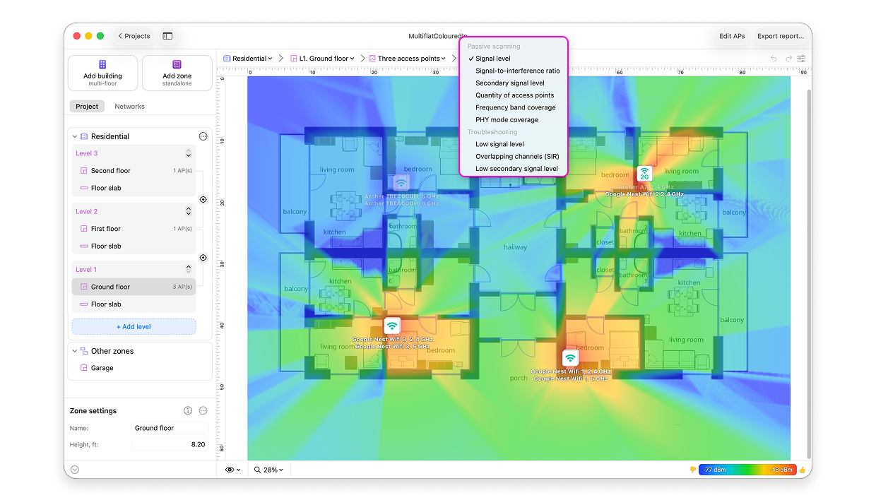
With NetSpot 3 and higher you can benefit mightily from Wi-Fi Planning mode, aka Predictive Wi-Fi site surveys. This mode allows you to create a layout of your surveyed site complemented with the structural components like walls, doors, windows, and their materials. This allows generating visually comprehensive WiFi heatmaps of a future WiFi coverage with all possible signal obstructions taken into consideration.
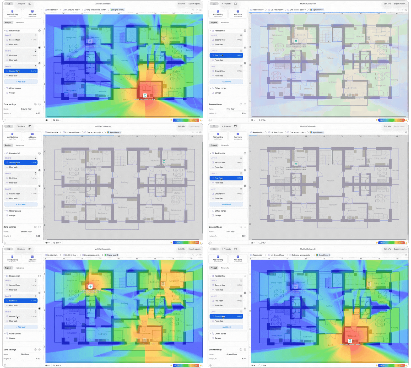
Starting with NetSpot 6 you can create WiFi design for multi-storey buildings for a provisional representation of how the WiFi signal will spread vertically and horizontally through a building.
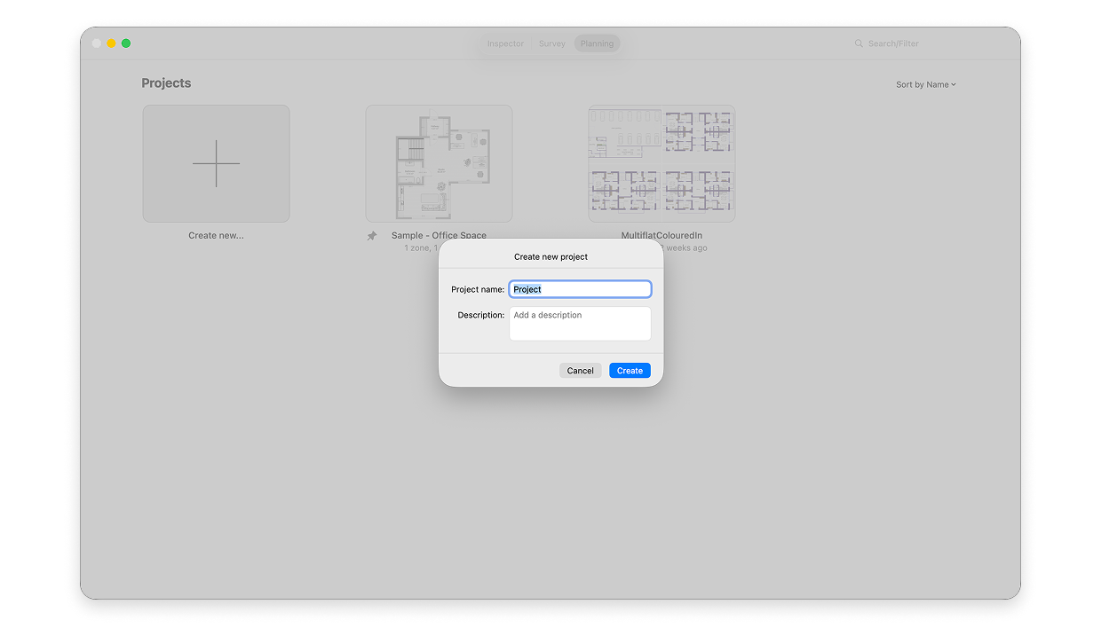
Click the Create New… option on the project home screen and choose the name of your project. You can also add a description for your convenience.
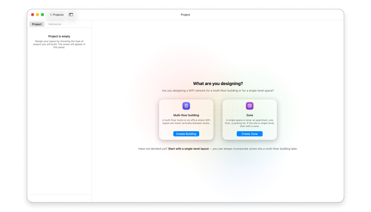
Depending on your project choose either a multi-floor building or start with creating one zone for a single-level space.
If you choose the single Zone option, you can skip to steps 9 through 13 and then proceed to the How to place the APs section.
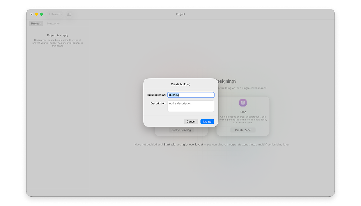
Choose the Multi-floor building option and name your building. You can also add a description for your convenience.
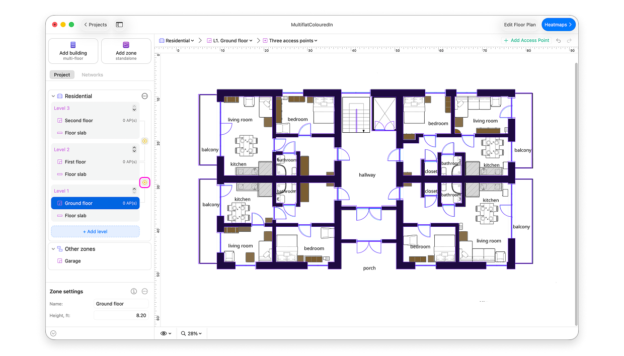
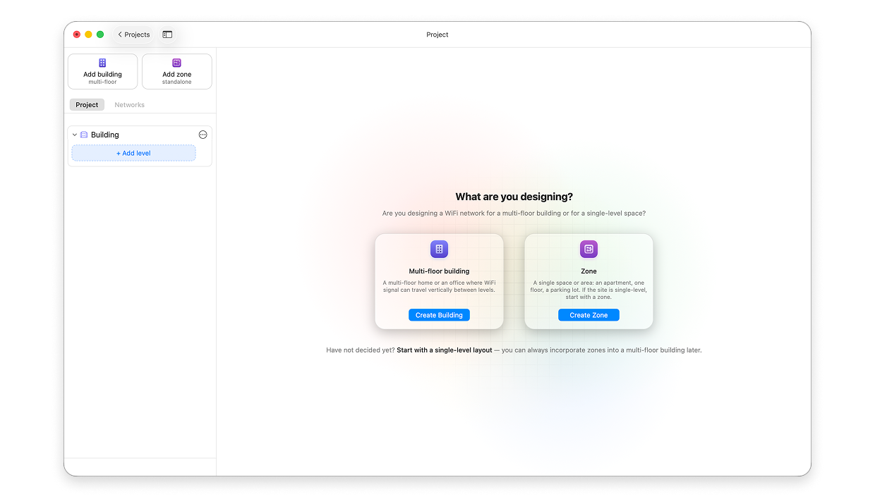
You will see your created building in the left panel.
Now it is time to add levels to your building. Use +Add level in the left panel.
Creating a level or a zone in a building
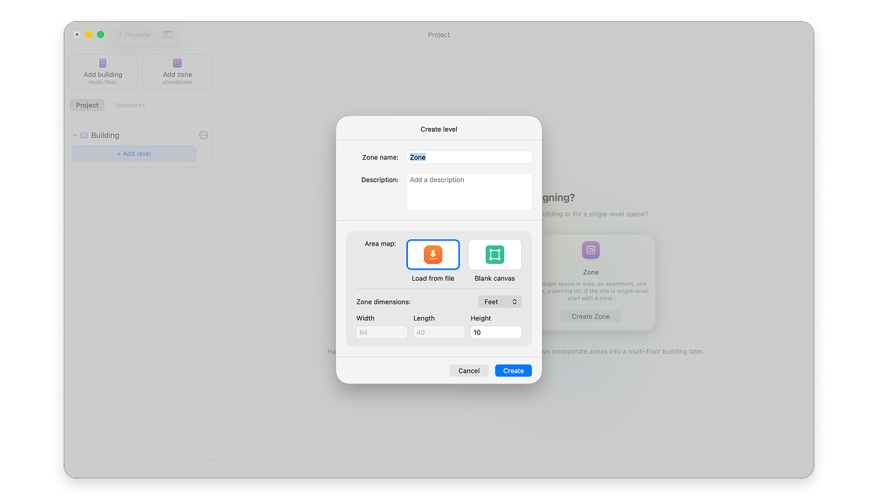
Adding a new level is a lot like adding a new zone to your project. In the window that pops up add the name and description. Choose whether you’ll be uploading an already existing map/floor plan or creating a layout from scratch. Uploading a map file (a photo or a blueprint) is recommended since it gives you the exact idea where to place the structural elements of the layout. Enter the zone dimensions including the height. Click Create.
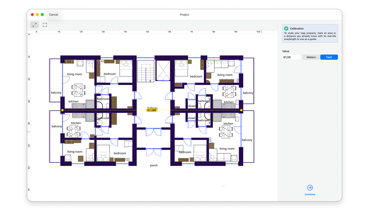
In case you are creating a layout from blank, you’ll set the canvas size before clicking Create. In case of an uploaded file, you’ll need to calibrate your map for correct scaling after clicking Create. To calibrate the map, use either a line or an area on the map that you can correctly state the measurements for.
Once done calibrating, it is time to “build” your space using the toolset in the top menu — doors, windows, walls, rectangle of walls, and racks. These are important, because they have a direct effect on wireless signal distribution through a designated space.
Useful tip: In NetSpot for Mac there is a possibility to switch off the walls alignment and snapping to already existing walls by pressing and holding the Option key, ⌥, while placing walls on the floor plan.
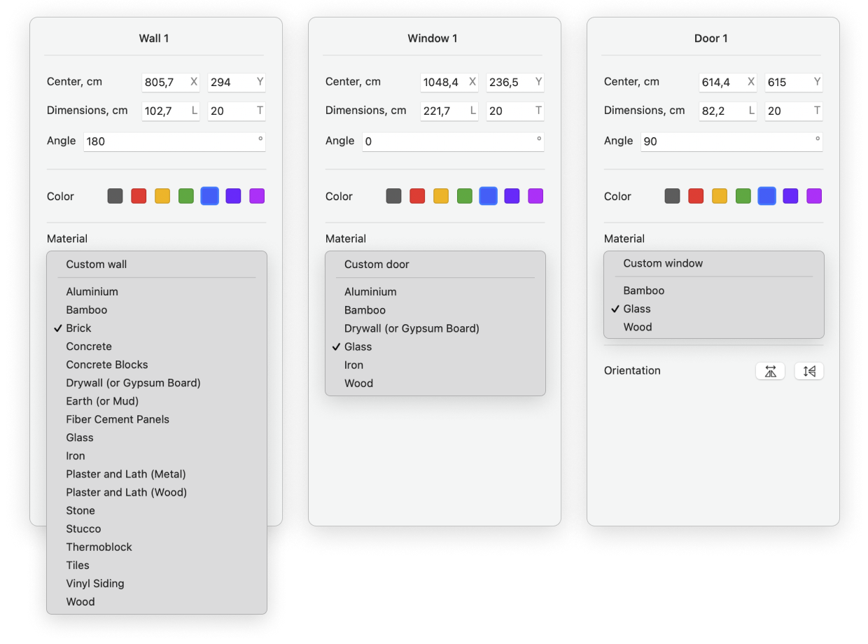
Set the materials for each building block of your surveyed area. You can set your own custom material with specific reflection and absorption values, or use presets on the list for the most commonly used types of materials. We have prepared a dedicated post on reflection and absorption, so please make sure to read it to choose the best values for your project. You can also set colors for various types of building elements to easily identify the elements with different characteristics.
NB: Use the selection tool at the top to select each structural item and manage its properties in the side panel to the right of the canvas.
After all building elements have been placed and their properties set, click Start planning.
Note: You can export the floor plan that you created to a PNG file to later use it for a survey of an already existing WiFi network.
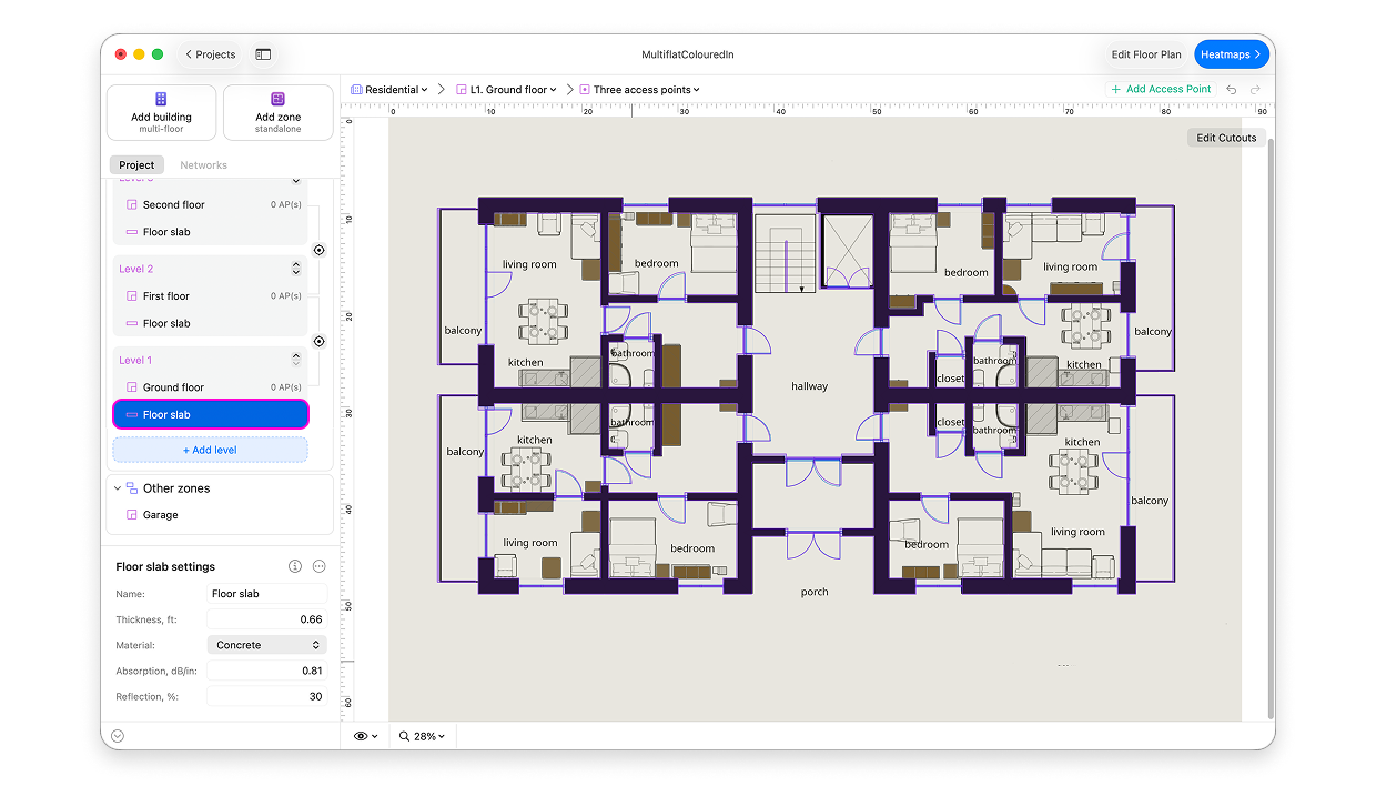
The floor materials between the building levels are important for signal distribution. Click the Floor slab option for every level and set the thickness of the floor slab as well as its material. If the material you are looking for is not on the list, select custom and enter the reflection and absorption values corresponding with the material your floor system is made of.
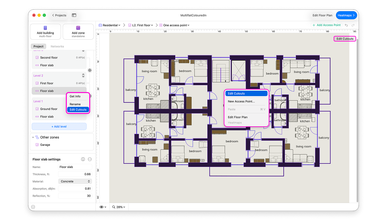
In order to model the signal spread accurately through openings between the floors use the Cutout Editing option to incorporate stairwells or atriums into your design. Cutout Editing can be found in the right upper corner or through the context menu by clicking where the cutout is needed on the map. It becomes active when you select the floor slab you will be adding a cutout to.
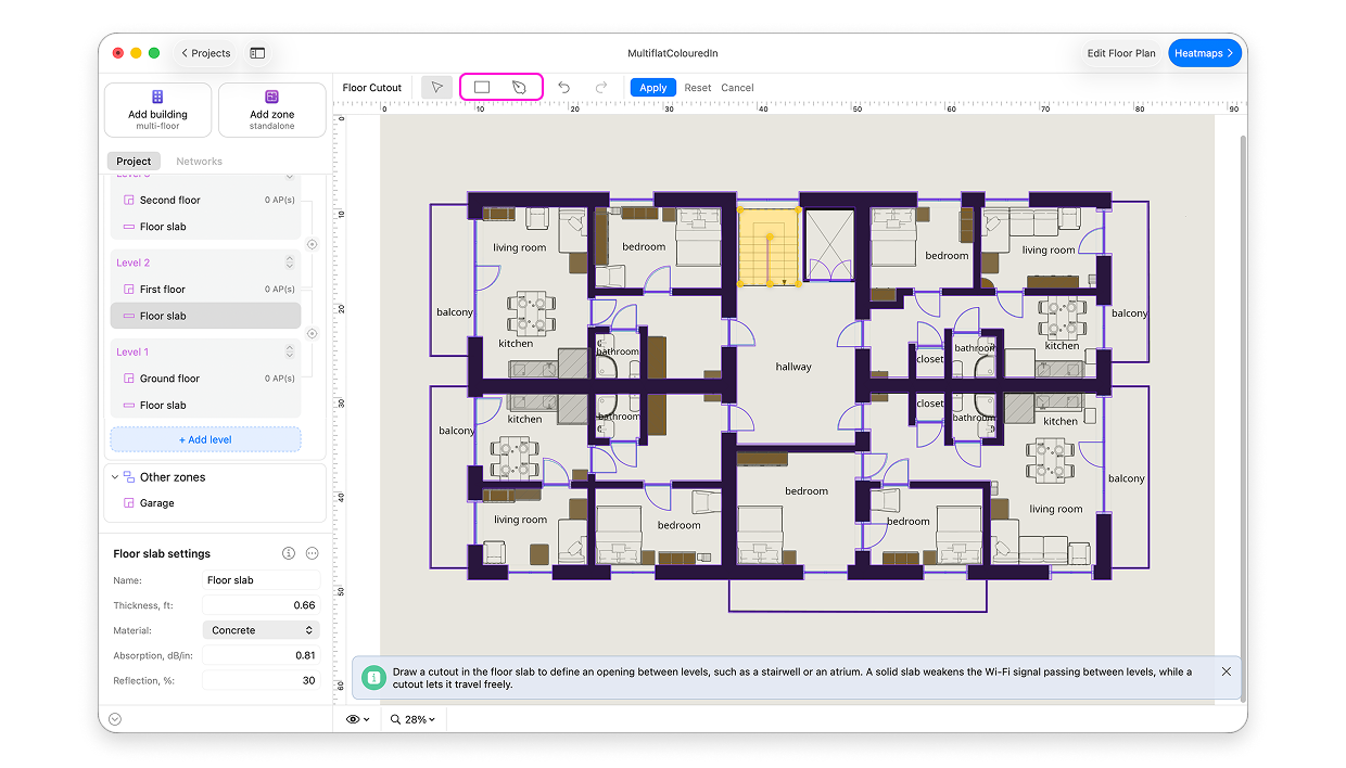
Choose the cutout style from the menu panel – either freestyle custom area or a rectangle.
Once you are done adding the cutouts, click Apply.
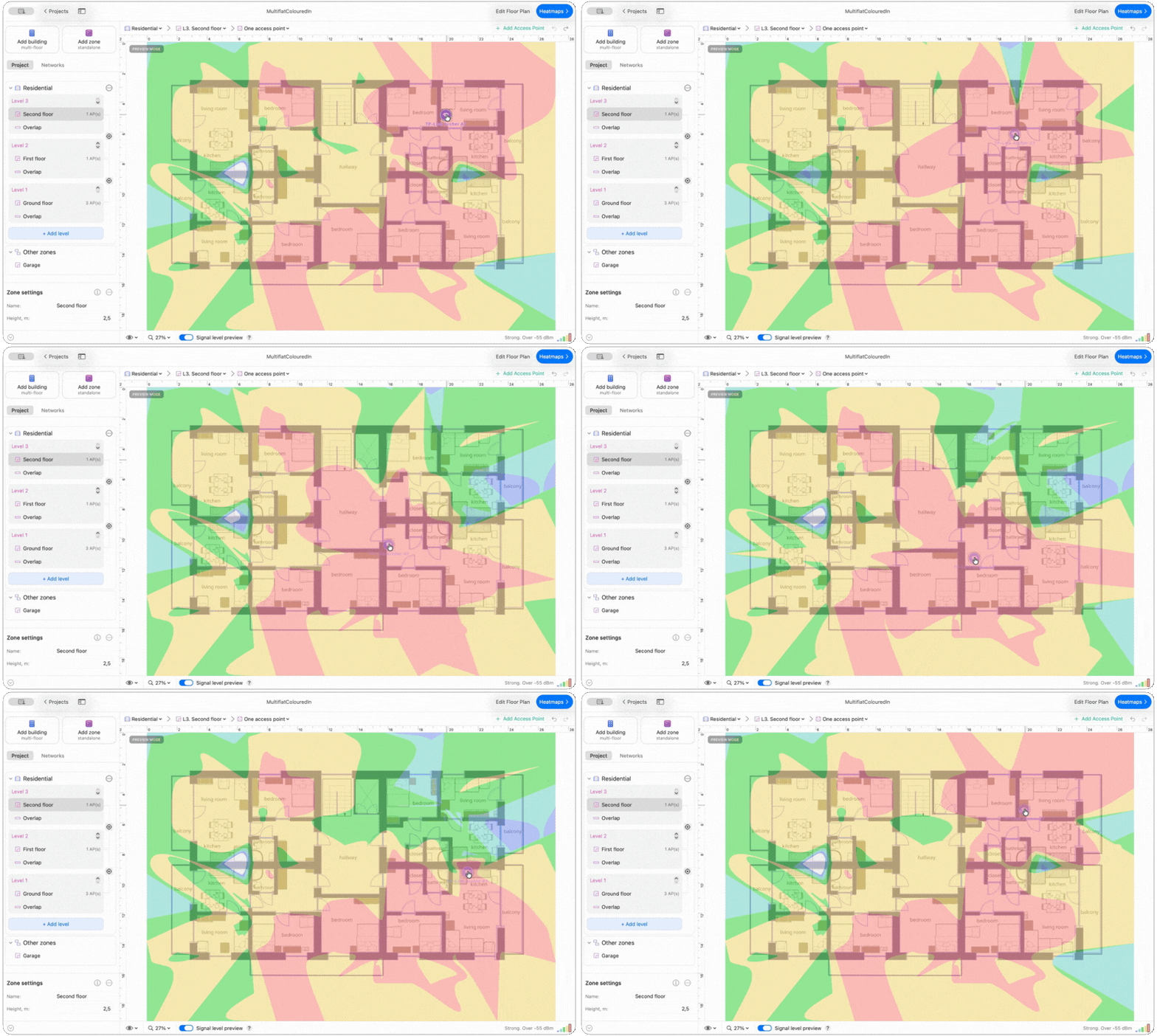
Good to know: if an AP is placed very close under the cutout area, the strongest signal will not be in the cutout area, but actually at an angle due to the specifics of wireless signal spreading. See the screenshot below for reference.
Add new floors to your project just the same way you did in steps 9-15.
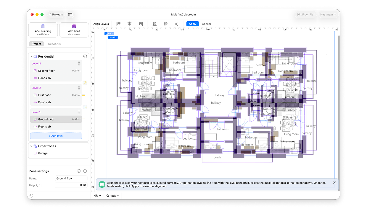
After all the floors have been added to the project, they need to be aligned vertically to ensure correct signal spreading and bleeding. Use the Align floors with each other option that you can see in the right panel between the floors.
You will immediately see the aligned floors highlighted on the plan with one floor semi-tranparent for a better visual experience.
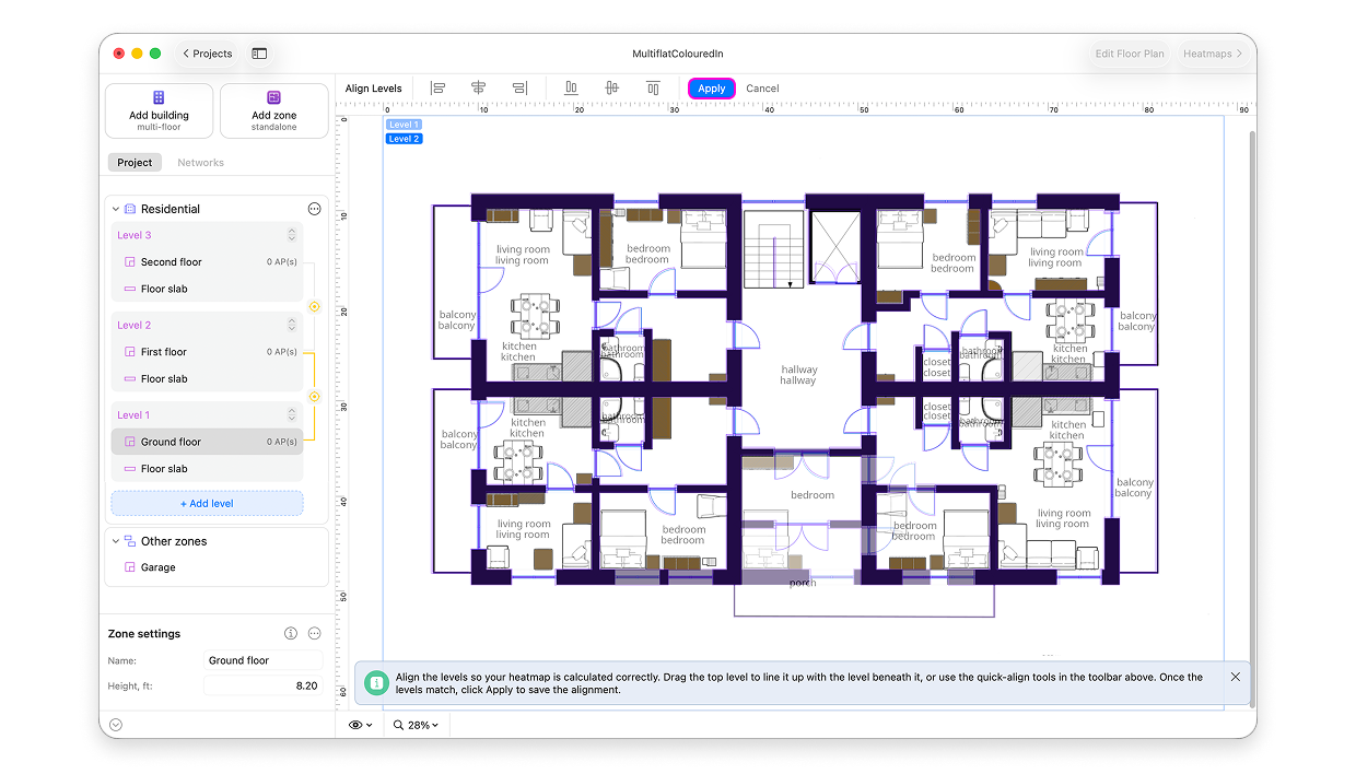
Make sure to match up the structural elements. If the floorplans for different levels are the same size and scaled properly, then it should be quite easy to match the levels. You can also use the Align Levels tool in the upper panel.
Once you are happy with the alignment, click Apply in the upper panel.
Note: You can drag the levels to reorder them. You will need to align them again after reordering.
Important: you won’t be able to generate heatmaps until the levels are aligned.
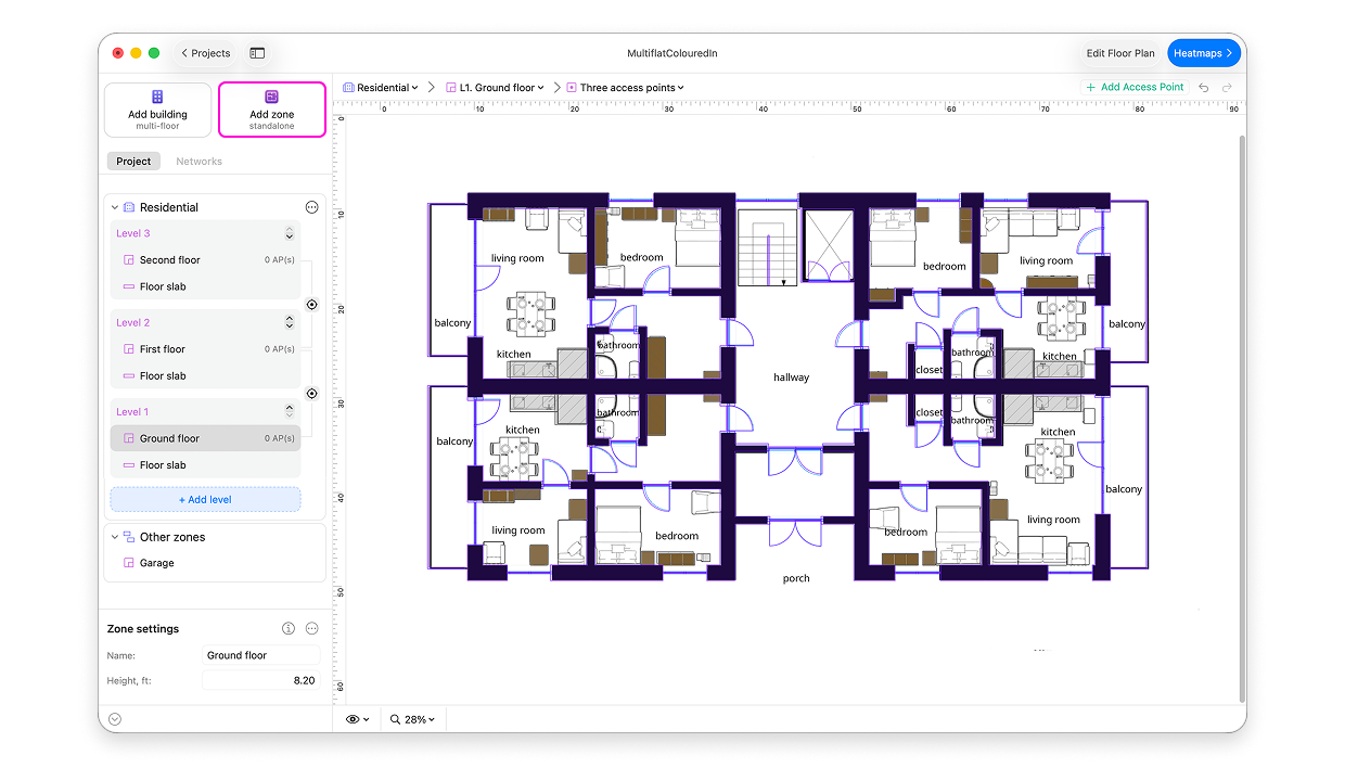
Note: There is a possibility to add additional zones to a multi-floor building, e.g. when you need to add a parking lot to your project. To do that use the Add Zone (standalone) option in the left panel and follow the familiar process of creating a new zone.
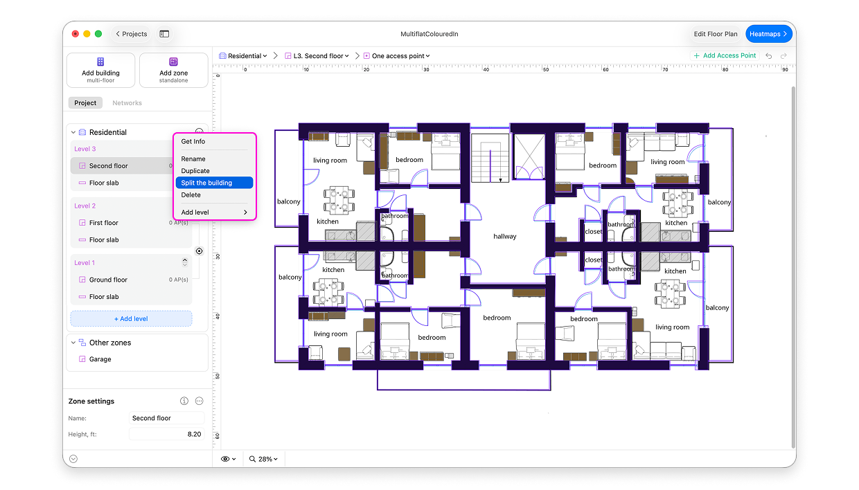
Any multi floor building can be split into independent zones. Click on the three dots next to the name of the building -> Split the building.
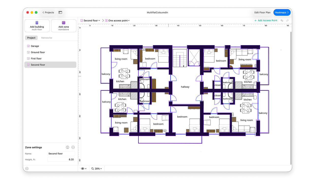
The levels will be moved into the Other zones section where they will show up simply as single-level zones like those in single-level projects.
How to place the APs
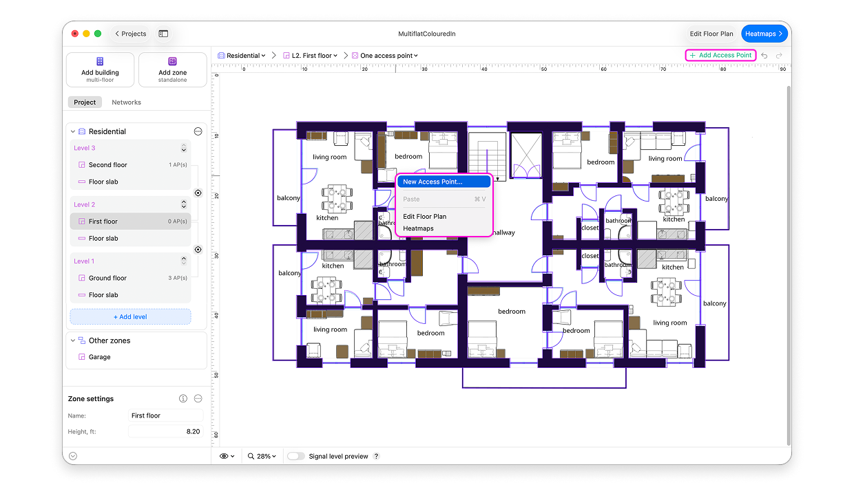
Now it’s time to start placing the APs in the surveyed space.
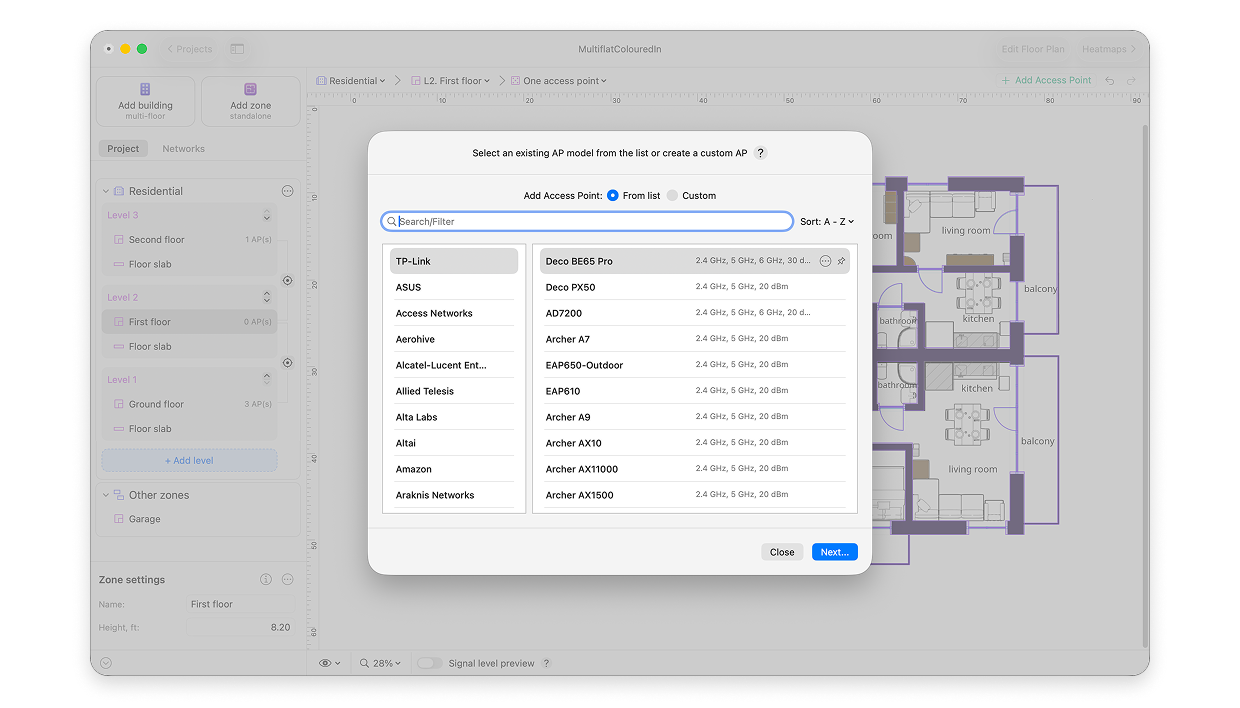
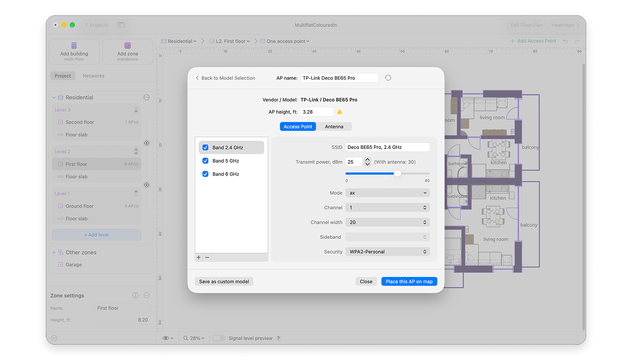
Add your first AP where you think fit and select an AP brand and model from a pop-up menu.
Specify AP’s desired settings.
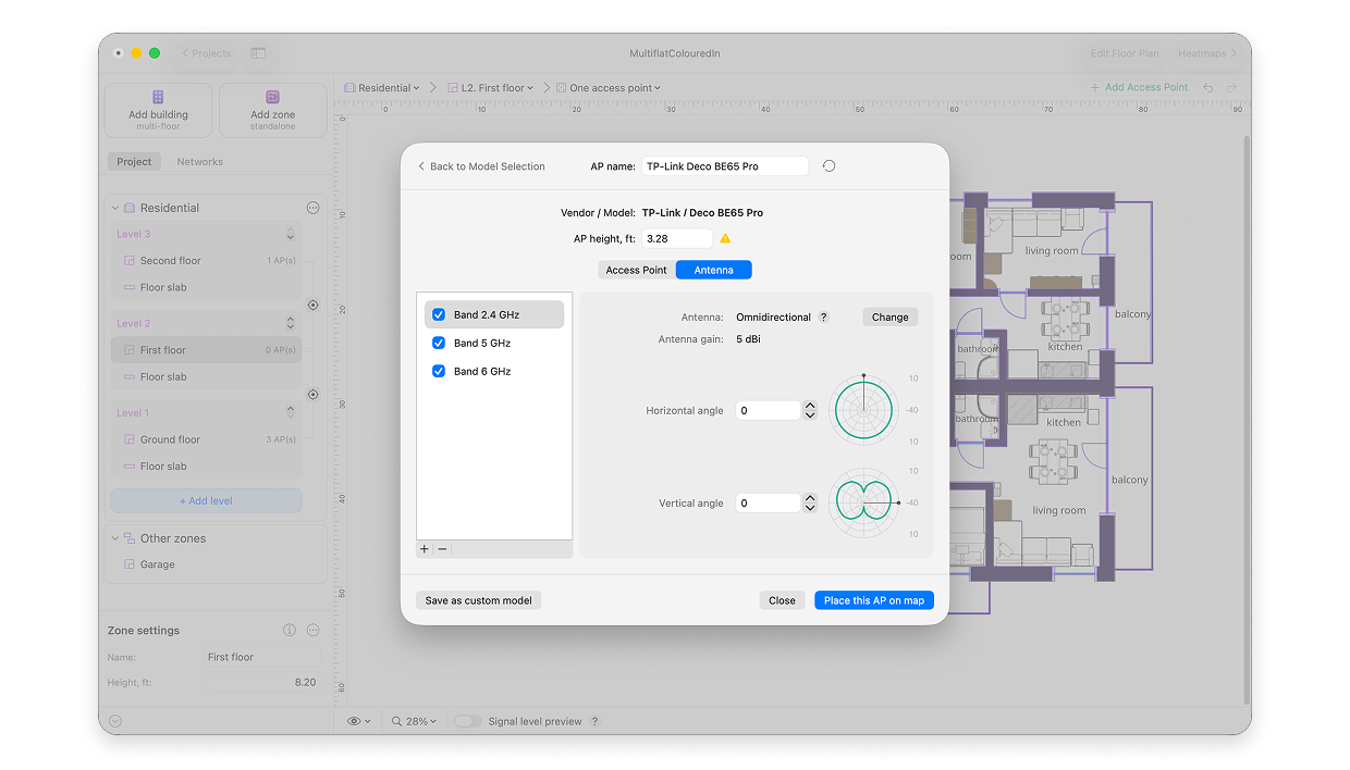
When adding an AP, you can set the antenna properties for it or import the antenna information from a file.
If you don’t already have an antenna file, you can download it from an AP vendor’s official website. For example, Ubiquiti antenna patterns are available on their website. If you cannot find an antenna file on a vendor’s website, try contacting their support.
There are also general databases with antenna pattern files that you can use, like this one or this one.
File types can have various extensions. NetSpot supports .json, .ant, .ana, .msi, .adf, and .prn.
There are resources that allow you to create your own antenna patterns; however, we do not recommend doing this due to the complexity and depth of radio engineering data involved.
Not finding certain APs in NetSpot? Just drop us a line with the desired AP brands and models, and we’ll add them promptly.
Check the list of APs below to see if your model is already supported.
Brand
Model
Access Networks
A350
Access Networks
A550
Access Networks
A650
Access Networks
A750
Brand
Model
Aerohive
AP122
Aerohive
AP230
Brand
Model
Alcatel-Lucent Enterprise
AP1201
Alcatel-Lucent Enterprise
AP1261
Alcatel-Lucent Enterprise
AP1311
Alcatel-Lucent Enterprise
AP1321
Alcatel-Lucent Enterprise
AP1361
Alcatel-Lucent Enterprise
AP1301
Alcatel-Lucent Enterprise
AP1331
Alcatel-Lucent Enterprise
AP1351
Alcatel-Lucent Enterprise
AP1411
Alcatel-Lucent Enterprise
AP1431
Alcatel-Lucent Enterprise
AP1451
Alcatel-Lucent Enterprise
AP1511
Alcatel-Lucent Enterprise
AP1521
Brand
Model
Allied Telesis
TQ5403
Allied Telesis
TQ6602
Allied Telesis
TQ6602 GEN2
Allied Telesis
TQ6702 GEN2
Allied Telesis
TQ6702 GEN2-R
Allied Telesis
TQ6702e GEN2
Brand
Model
Alta Labs
AP6
Alta Labs
AP6 Pro
Alta Labs
AP6W
Brand
Model
Altai
A2
Altai
A2x
Altai
A3-Ei
Altai
A8-Ein (ac)
Altai
A8in (ac)
Altai
A8-n (ac)
Altai
AX600-S
Altai
AX600-X
Altai
C1an
Altai
C1n
Altai
C1xan
Altai
C1xn+
Altai
C260-S
Altai
C2s
Altai
CX200
Altai
CX600
Altai
IX600
Altai
VX200
Brand
Model
Amazon
Eero 6
Amazon
Eero 7
Amazon
Eero Max 7
Amazon
Eero PoE 6
Amazon
Eero Pro 6
Amazon
Eero Pro 6E
Amazon
Eero Pro 7
Amazon
Eero Outdoor 7
Brand
Model
Araknis Networks
AN-320-AP-I
Araknis Networks
AN-510-AP-I-AC
Araknis Networks
AN-510-AP-IW-AC
Araknis Networks
AN-520-AP-I
Araknis Networks
AN-520-AP-O
Araknis Networks
AN-700-AP-O-AC
Araknis Networks
AN-810-AP-I-AC
Araknis Networks
AN-820-AP-I
Brand
Model
Arista
C-260
Arista
C-360
Arista
C-460
Brand
Model
ASUS
ROG Rapture GT-AC2900
ASUS
ROG Rapture GT-AC5300
ASUS
ROG Rapture GT-AX11000
ASUS
ROG Rapture GT-AXE11000
ASUS
ROG Rapture GT-BE98 Pro
ASUS
ROG STRIX GS-AX3000
ASUS
ROG STRIX GS-AX5400
ASUS
RT-AX1800S
ASUS
RT-AX3000
ASUS
RT-AX55
ASUS
RT-AX56U
ASUS
RT-AX58U
ASUS
RT-AX82U
ASUS
RT-AX86U
ASUS
RT-AX88U
ASUS
RT-AX92U
ASUS
RT-BE88U
ASUS
RT-BE96U
ASUS
TUF-AX5400
ASUS
ZenWiFi (ET8)
ASUS
ZenWiFi BD5
ASUS
ZenWiFi Pro (ET12)
Brand
Model
AT&T
5268AC
AT&T
BGW210
AT&T
BGW320
AT&T
NVG599
Brand
Model
AVM
FRITZ!Box 7530
AVM
FRITZ!Box 5690 Pro
Brand
Model
Calix
GigaSpire BLAST 7u10t
Calix
GigaSpire BLAST 7u10txg
Calix
GigaSpire BLAST u4
Calix
GigaSpire BLAST u4g
Calix
GigaSpire BLAST u4hm
Calix
GigaSpire BLAST u4m
Calix
GigaSpire BLAST u6.1
Calix
GigaSpire BLAST u6.2
Calix
GigaSpire BLAST u6e
Calix
GigaSpire BLAST u6me
Calix
GigaSpire BLAST u6t
Calix
GigaSpire BLAST u6txg
Calix
GigaSpire BLAST u10xe
Calix
GigaPro p6dx
Calix
GigaPro p6he
Brand
Model
Cambium Networks
cnPilot e410
Cambium Networks
cnPilot e425H
Cambium Networks
cnPilot e430H
Cambium Networks
cnPilot e500
Cambium Networks
cnPilot e501S
Cambium Networks
cnPilot e502S
Cambium Networks
cnPilot e505
Cambium Networks
cnPilot e510
Cambium Networks
cnPilot e600
Cambium Networks
cnPilot e700
Cambium Networks
cnPilot r190
Cambium Networks
cnPilot r195P/td>
Cambium Networks
cnPilot r195W
Cambium Networks
cnPilot r200P
Cambium Networks
cnPilot r201
Cambium Networks
XE3-4
Cambium Networks
XE3-4TN
Cambium Networks
XE5-8
Cambium Networks
XV2-2T0
Cambium Networks
XV2-2T1
Cambium Networks
XV2-2X
Cambium Networks
XV2-21X
Cambium Networks
XV2-22H
Cambium Networks
XV2-23T
Cambium Networks
XV3-8
Brand
Model
CipherLab
RK95
CipherLab
RS35
Brand
Model
Cisco
AIR-AP1852I
Cisco
AIR-AP2802E
Cisco
AIR-AP3802E
Cisco
Aironet 1800
Cisco
Aironet 1810
Cisco
Aironet 2600
Cisco
Aironet 2700
Cisco
Aironet 2800
Cisco
Aironet 3700
Cisco
Aironet 3800
Cisco
Aironet 4800
Cisco
Business 240AC
Cisco
Catalyst 9105AXI
Cisco
Catalyst 9115
Cisco
Catalyst 9120AX
Cisco
Catalyst 9124AXE
Cisco
Catalyst 9124AXI
Cisco
Catalyst 9130AXE
Cisco
Catalyst 9130AXI-B
Cisco
Catalyst 9136I
Cisco
Catalyst IW9167
Cisco
Catalyst IW9167E
Cisco
Catalyst IW9167I
Cisco
CBW150AX
Cisco
CBW151AXM
Cisco
CW9162
Cisco
CW9162I
Cisco
CW9163E
Cisco
CW9164
Cisco
CW9166D1
Cisco
CW9166I
Cisco
CW9172H
Cisco
CW9172I
Cisco
CW9176D1
Cisco
CW9176I
Cisco
CW9178I
Cisco
CW9179F
Cisco
CW9174I
Cisco
Meraki CW9164
Cisco
Meraki CW9166
Cisco
Meraki MR28
Cisco
Meraki MR30H
Cisco
Meraki MR32
Cisco
Meraki MR33
Cisco
Meraki MR34
Cisco
Meraki MR36
Cisco
Meraki MR36H
Cisco
Meraki MR42
Cisco
Meraki MR44
Cisco
Meraki MR46
Cisco
Meraki MR46E
Cisco
Meraki MR52
Cisco
Meraki MR56
Cisco
Meraki MR57
Cisco
Meraki MR70
Cisco
Meraki MR72
Cisco
Meraki MR74
Cisco
Meraki MR76
Cisco
Meraki MR78
Cisco
Meraki MR84
Cisco
Meraki MR86
Cisco
Meraki MX68W
Brand
Model
Datto
AP440
Datto
AP840
Brand
Model
D-Link
DAP-3666
D-Link
DAP-X2810
D-Link
DIR-X1560
D-Link
DIR-X3260
D-Link
DIR-X5460
D-Link
DIR 3060 EXO AC3000
Brand
Model
DrayTek
VigorAP 1060C
DrayTek
VigorAP 1062C
DrayTek
VigorAP 800
DrayTek
VigorAP 903
Brand
Model
EnGenius
ECW120
EnGenius
ECW215
EnGenius
ECW220
EnGenius
ECW230
EnGenius
ECW260
EnGenius
ECW270
EnGenius
ECW520
EnGenius
ECW536
EnGenius
EWS276-FIT
EnGenius
EWS310AP
EnGenius
EWS356-FIT
EnGenius
EWS377-FIT
EnGenius
EWS850-FIT
Brand
Model
Extreme Networks
AP305C
Extreme Networks
AP305CX
Extreme Networks
AP3000
Extreme Networks
AP3000X
Extreme Networks
AP310e
Extreme Networks
AP310i
Extreme Networks
AP4000
Extreme Networks
AP410C
Extreme Networks
AP410e
Extreme Networks
AP410i
Extreme Networks
AP460C
Extreme Networks
AP460S12C
Extreme Networks
AP460S6C
Extreme Networks
AP5010
Extreme Networks
AP5020
Extreme Networks
AP510C
Extreme Networks
AP510CX
Extreme Networks
AP6532
Extreme Networks
AP7522
Brand
Model
Fortinet
FortiAP 221E
Fortinet
FortiAP 223E
Fortinet
FortiAP 231F
Fortinet
FortiAP 231G
Fortinet
FortiAP 231K
Fortinet
FortiAP 233G
Fortinet
FortiAP 234F
Fortinet
FortiAP 234G
Fortinet
FortiAP 23JF
Fortinet
FortiAP 23JK
Fortinet
FortiAP 241K
Fortinet
FortiAP 243K
Fortinet
FortiAP 421E
Fortinet
FortiAP 231F
Fortinet
FortiAP 431G
Fortinet
FortiAP 432F
Fortinet
FortiAP 432FR
Fortinet
FortiAP 432G
Fortinet
FortiAP 433F
Fortinet
FortiAP 433G
Fortinet
FortiAP 441K
Fortinet
FortiAP 443K
Fortinet
FortiAP 831F
Fortinet
FortiAP 832E
Fortinet
FortiAP U231F
Fortinet
FortiAP U234F
Fortinet
FortiAP U321EV
Fortinet
FortiAP U431F
Fortinet
FortiAP 432F
Fortinet
FortiAP U433F
Fortinet
FortiAP 822E
Brand
Model
Freebox
Revolution
Freebox
Ultra
Brand
Model
Galgus
IX450
Galgus
IX850
Galgus
OX451
Brand
Model
Google
Nest Wifi
Brand
Model
Grandstream
GWN7600
Grandstream
GWN7600LR
Grandstream
GWN7602
Grandstream
GWN7605
Grandstream
GWN7605LR
Grandstream
GWN7610
Grandstream
GWN7615
Grandstream
GWN7624
Grandstream
GWN7625
Grandstream
GWN7630
Grandstream
GWN7630LR
Grandstream
GWN7660
Grandstream
GWN7660LR
Grandstream
GWN7661
Grandstream
GWN7662
Grandstream
GWN7664
Grandstream
GWN7664E
Grandstream
GWN7664ELR
Grandstream
GWN7664LR
Grandstream
GWN7665
Grandstream
GWN7670
Grandstream
GWN7672
Brand
Model
H3C
WA4320-ACN-E
H3C
WA530-WW
H3C
WA6320
H3C
WA7539
Brand
Model
HPE
Aruba AP11
HPE
Aruba AP12
HPE
Aruba AP15
HPE
Aruba AP17
HPE
Aruba AP21
HPE
Aruba AP22
HPE
Aruba AP25
HPE
Aruba AP27
HPE
Aruba AP32
HPE
Aruba AP-303
HPE
Aruba AP-303H
HPE
Aruba AP-305
HPE
Aruba AP-315
HPE
Aruba AP-325
HPE
Aruba AP-374
HPE
Aruba AP-503
HPE
Aruba AP-503H
HPE
Aruba AP-504
HPE
Aruba AP-505
HPE
Aruba AP-505 RW
HPE
Aruba AP-505H
HPE
Aruba AP-514
HPE
Aruba AP-515
HPE
Aruba AP-515 RW
HPE
Aruba AP-518
HPE
Aruba AP-534
HPE
Aruba AP-535
HPE
Aruba AP-535 RW
HPE
Aruba AP-555
HPE
Aruba AP-565
HPE
Aruba AP-565 RW
HPE
Aruba AP-565EX
HPE
Aruba AP-567
HPE
Aruba AP-574
HPE
Aruba AP-575
HPE
Aruba AP-577
HPE
Aruba AP-587
HPE
Aruba AP-615
HPE
Aruba AP-615 RW
HPE
Aruba AP-635 RW
HPE
Aruba AP-655
HPE
Aruba AP-677
HPE
Aruba AP-725
HPE
Aruba AP-735
HPE
Aruba AP-755
HPE
Aruba IAP-103
HPE
Aruba IAP-207
HPE
Aruba IAP-225
HPE
Aruba IAP-325
HPE
Aruba IAP-365
HPE
Aruba IAP-367
HPE
Aruba 360
HPE
Aruba 530
HPE
Aruba 550
HPE
Aruba 580
HPE
Aruba 580EX
HPE
Aruba 600R
HPE
Aruba 610
HPE
Aruba 630
HPE
Aruba 650
HPE
Aruba 670
HPE
Aruba 730
HPE
Aruba 760
Brand
Model
Indio Networks
UM-125AX
Indio Networks
UM-225AX
Indio Networks
UM-305AC
Indio Networks
UM-325AC
Indio Networks
UM-325AX
Indio Networks
UM-510AC
Indio Networks
UM-525AX-M
Indio Networks
UM-525AX-P
Indio Networks
UM-530AC
Brand
Model
Intelbras
AP 360
Intelbras
AP 1250 AC Max
Intelbras
AP 1350 AC
Intelbras
AP 1350 AC-S
Intelbras
AP 1800 AX
Intelbras
AP 3000 AX
Intelbras
AP 3620
Intelbras
AP 3620H
Intelbras
AP 5620
Intelbras
AP 5620XDE
Intelbras
AP 5626
Intelbras
AP 5630
Intelbras
AP 7636
Intelbras
AP 7739
Brand
Model
Juniper Networks
AP12
Juniper Networks
AP21
Juniper Networks
AP24
Juniper Networks
AP32
Juniper Networks
AP33
Juniper Networks
AP34
Juniper Networks
AP41
Juniper Networks
AP43
Juniper Networks
AP43E
Juniper Networks
AP45
Juniper Networks
AP61
Juniper Networks
AP63
Juniper Networks
AP64
Brand
Model
LANCOM
LW-600
LANCOM
LX-6200
LANCOM
LX-6400
LANCOM
LX-7200E
LANCOM
LX-7300
LANCOM
LX-7500
LANCOM
OW-602
Brand
Model
Linksys
MX8500
Linksys
WHW0303
Brand
Model
Luxul
MK-10
Luxul
MN-10
Luxul
P40
Luxul
WS-80
Luxul
WS-250
Luxul
WS-260
Luxul
XAP-810
Luxul
XAP-1440
Luxul
XAP-1510
Luxul
XAP-1610
Luxul
XWR-1200
Luxul
XWR-3150
Luxul
XWS-2510
Luxul
XWS-2520
Luxul
XWS-2610
Luxul
XWS-2620
Brand
Model
Mercusys
AC12G
Brand
Model
MikroTik
Audience
MikroTik
cAP
MikroTik
cAP ac
MikroTik
cAP ax
MikroTik
cAP lite
MikroTik
cAP XL ac
MikroTik
Chateau LTE6
MikroTik
Chateau LTE6 ax
MikroTik
Chateau LTE6-US
MikroTik
Chateau LTE12
MikroTik
Chateau LTE18 ax
MikroTik
Chateau 5G
MikroTik
Chateau 5G ax
MikroTik
hAP
MikroTik
hAP ac
MikroTik
hAP ac lite
MikroTik
hAP ac lite TC
MikroTik
hAP ac2
MikroTik
hAP ac3
MikroTik
hAP ax lite
MikroTik
hAP ax lite LTE6
MikroTik
hAP ax2
MikroTik
hAP ax3
MikroTik
hAP lite
MikroTik
hAP lite TC
MikroTik
KNOT
MikroTik
L009UiGS-2HaxD-IN
MikroTik
mANTBox ax 15s
MikroTik
mAP
MikroTik
mAP lite
MikroTik
NetMetal ax
MikroTik
OmniTIK 5 PoE ac
MikroTik
RB4011iGS+5HacQ2HnD-IN
MikroTik
RB951Ui-2HnD
MikroTik
wAP ac
MikroTik
wAP ax
MikroTik
wAP Ra
Brand
Model
Netgear
Nighthawk AX6
Netgear
RBE370
Netgear
RBE770
Netgear
RBE771
Netgear
RBE870
Netgear
RBE970
Netgear
RBE973
Netgear
RBKE963
Netgear
RBR850
Netgear
RBS850
Netgear
WAC104
Netgear
WAC124
Netgear
WAC510
Netgear
WAC540
Netgear
WAX202
Netgear
WAX204
Netgear
WAX206
Netgear
WAX218
Netgear
WAX220
Netgear
WAX610
Netgear
WAX610Y
Netgear
WAX615
Netgear
WAX620
Netgear
WAX625
Netgear
WAX630
Netgear
WAX630E
Netgear
WBE718
Netgear
WBE758
Brand
Model
Netis
MW5230
Brand
Model
Pakedge
WA-4200-1
Brand
Model
Peplink
AP One Mini
Peplink
B One
Peplink
B One 5G
Peplink
B One Plus
Peplink
MAX Transit Duo Pro
Brand
Model
Plume
SuperPod
Plume
SuperPod with WiFi 6
Plume
SuperPod with WiFi 6E
Brand
Model
Quantum
QN-H-220
Quantum
QN-H-245
Quantum
QN-I-210
Quantum
QN-I-220
Quantum
QN-I-270
Quantum
QN-I-280
Quantum
QN-I-470
Quantum
QN-I-490
Quantum
QN-I-870
Quantum
QN-O-230
Quantum
QN-O-240
Quantum
QN-O-490
Brand
Model
Ruckus
H350
Ruckus
H550
Ruckus
R320
Ruckus
R350
Ruckus
R370
Ruckus
R510
Ruckus
R550
Ruckus
R560
Ruckus
R600
Ruckus
R650
Ruckus
R670
Ruckus
R710
Ruckus
R750
Ruckus
R760
Ruckus
R770
Ruckus
R850
Ruckus
T310
Ruckus
T310c
Ruckus
T350
Ruckus
T350c
Ruckus
T670sn
Ruckus
T750
Ruckus
ZF7363
Ruckus
ZF7372
Brand
Model
Ruijie Networks
RG-AP180-I
Ruijie Networks
RG-AP180(V3)
Ruijie Networks
RG-AP680-CD(V3)
Ruijie Networks
RG-AP680-AR
Ruijie Networks
RG-AP680-IO
Ruijie Networks
RG-AP680-O(V3)
Ruijie Networks
RG-AP810-I
Ruijie Networks
RG-AP820-AR(V3)
Ruijie Networks
RG-AP820-I
Ruijie Networks
RG-AP840-I(V2)
Ruijie Networks
RG-AP850-AR(V3)
Ruijie Networks
RG-AP880-AR
Ruijie Networks
RG-AP880-E
Ruijie Networks
RG-EW1300G
Ruijie Networks
RG-RAP1200(F)
Ruijie Networks
RG-RAP1200(P)
Ruijie Networks
RG-RAP1201
Ruijie Networks
RG-RAP1260
Ruijie Networks
RG-RAP1261
Ruijie Networks
RG-RAP2200(E)
Ruijie Networks
RG-RAP2200(F)
Ruijie Networks
RG-RAP2260
Ruijie Networks
RG-RAP2260(E)
Ruijie Networks
RG-RAP2260(G)
Ruijie Networks
RG-RAP2260(H)
Ruijie Networks
RG-RAP2266
Ruijie Networks
RG-RAP62
Ruijie Networks
RG-RAP62-OD
Ruijie Networks
RG-RAP6260(G)
Ruijie Networks
RG-RAP6262(G)
Ruijie Networks
RG-RAP72
Ruijie Networks
RG-RAP73HD
Brand
Model
Siemens
6GK5763-1AL00-7DA0
Siemens
SCALANCE WAM766-1
Brand
Model
Sky
SR203
Brand
Model
SonicWall
SonicWave 621
SonicWall
SonicWave 641
SonicWall
SonicWave 681
Brand
Model
Sophos
AP15
Sophos
AP15C
Sophos
AP55
Sophos
AP55C
Sophos
AP100
Sophos
AP100C
Sophos
AP100X
Sophos
APX120
Sophos
APX320
Sophos
APX320X
Sophos
APX530
Sophos
APX7420
Sophos
AP6 420
Sophos
AP6 420E
Sophos
AP6 420X
Sophos
AP6 840
Sophos
AP6 840E
Brand
Model
Starlink
Gen 2
Starlink
Gen 3
Brand
Model
Synology
RT6600ax
Brand
Model
TELTONIKA
TAP200
Brand
Model
Tenda
TX9
Brand
Model
Todaair
IN1251Y
Todaair
IN1335KYW-H
Todaair
IN3231YW
Todaair
INAX50Y-H
Todaair
TD-MRT45 V40
Brand
Model
TP-Link
AD7200
TP-Link
Archer AX10
TP-Link
Archer AX20
TP-Link
Archer AX21
TP-Link
Archer AX50
TP-Link
Archer AX55
TP-Link
Archer AX72
TP-Link
Archer AX73
TP-Link
Archer AX1500
TP-Link
Archer AX1800
TP-Link
Archer AX3000
TP-Link
Archer AX3200
TP-Link
Archer AX11000
TP-Link
Archer A7
TP-Link
Archer A9
TP-Link
Archer BE230
TP-Link
Archer BE550
TP-Link
Archer C7
TP-Link
Archer C90
TP-Link
Archer C1200
TP-Link
Archer GX90
TP-Link
Archer TBE400UH
TP-Link
AX90 (AX6600)
TP-Link
AX1800 EAP620 HD
TP-Link
Deco BE25
TP-Link
Deco BE63
TP-Link
Deco BE65
TP-Link
Deco BE65 Pro
TP-Link
Deco BE75
TP-Link
Deco BE85
TP-Link
Deco M5
TP-Link
Deco M9 Plus
TP-Link
Deco PX50
TP-Link
Deco W7200
TP-Link
Deco XE75
TP-Link
Deco XE75 Pro
TP-Link
Deco XE200
TP-Link
Deco X20
TP-Link
Deco X50
TP-Link
Deco X50-Outdoor
TP-Link
Deco X50-PoE
TP-Link
Deco X55
TP-Link
Deco X60
TP-Link
Deco X68
TP-Link
Deco X75
TP-Link
Deco X80
TP-Link
Deco X90
TP-Link
Deco X95
TP-Link
EAP110
TP-Link
EAP225-Outdoor
TP-Link
EAP610
TP-Link
EAP610-Outdoor
TP-Link
EAP613
TP-Link
EAP615-Wall
TP-Link
EAP623-Outdoor
TP-Link
EAP625-Outdoor
TP-Link
EAP650
TP-Link
EAP650-Outdoor
TP-Link
EAP650 D30-Outdoor
TP-Link
EAP653
TP-Link
EAP653 UR
TP-Link
EAP655-Wall
TP-Link
EAP660 HD
TP-Link
EAP670
TP-Link
EAP673
TP-Link
EAP683
TP-Link
EAP683 UR
TP-Link
EAP723
TP-Link
EAP725-Outdoor
TP-Link
EAP772-Outdoor
TP-Link
EAP773
TP-Link
EAP783
Brand
Model
TRENDnet
TEW-921DAP
TRENDnet
TEW-923DAP
TRENDnet
TEW-925DAP
Brand
Model
Ubiquiti
AirFiber 2X
Ubiquiti
AirFiber 5X HD
Ubiquiti
AmpliFi Alien
Ubiquiti
Amplifi HD
Ubiquiti
PowerBeam 5AC Gen2
Ubiquiti
PrismStation AC
Ubiquiti
Rocket M2
Ubiquiti
UBB
Ubiquiti
UBB-XG
Ubiquiti
UK-Ultra
Ubiquiti
UniFi AC EDU
Ubiquiti
UniFi AC HD
Ubiquiti
UniFi AC Lite
Ubiquiti
UniFi AC LR
Ubiquiti
UniFi AC Mesh
Ubiquiti
UniFi AC Mesh Pro
Ubiquiti
UniFi AC Pro AP
Ubiquiti
UniFi AC SHD
Ubiquiti
UniFi Dream Wall
Ubiquiti
UniFi Dream Router 7
Ubiquiti
UniFi E7
Ubiquiti
UniFi E7 Audience
Ubiquiti
UniFi E7 Campus
Ubiquiti
UniFi In-Wall HD
Ubiquiti
UniFi nanoHD
Ubiquiti
UniFi U6+
Ubiquiti
UniFi U6-Enterprise
Ubiquiti
UniFi U6-Enterprise-IW
Ubiquiti
UniFi U6-Extender
Ubiquiti
UniFi U6-IW
Ubiquiti
UniFi U6-Lite
Ubiquiti
UniFi U6-LR
Ubiquiti
UniFi U6-Mesh
Ubiquiti
UniFi U6-Mesh-Pro
Ubiquiti
UniFi U6-Pro
Ubiquiti
UniFi U7-Lite
Ubiquiti
UniFi U7-LR
Ubiquiti
UniFi U7-Outdoor
Ubiquiti
UniFi U7-Pro
Ubiquiti
UniFi U7-Pro-Max
Ubiquiti
UniFi U7-Pro-Outdoor
Ubiquiti
UniFi U7-Pro-Wall
Ubiquiti
UniFi U7-Pro-XGS
Ubiquiti
UniFi WiFi BaseStation XG
Ubiquiti
UniFi XG
Ubiquiti
UWB-XG
Brand
Model
VSOL
HG5063C-AX30-1Q
VSOL
V2801AX30C-A
Brand
Model
Vodafone
Ultra Hub 7
Brand
Model
WatchGuard
AP130
WatchGuard
AP230W
WatchGuard
AP325
WatchGuard
AP327X
WatchGuard
AP330
WatchGuard
AP332CR
WatchGuard
AP420
WatchGuard
AP430CR
WatchGuard
AP432
Brand
Model
Wi-Tek
WI-AP210-Lite(V2)
Wi-Tek
WI-AP216(V2)
Wi-Tek
WI-AP217-Lite(V2)
Wi-Tek
WI-AP217(V2)
Wi-Tek
WI-AP218AX-Lite(V2)
Wi-Tek
WI-AP218AX(V2)
Wi-Tek
WI-AP219AX-Lite(V2)
Wi-Tek
WI-AP219AX(V2)
Wi-Tek
WI-AP229BE
Wi-Tek
WI-AP316AX
Wi-Tek
WI-AP316AX-Lite
Wi-Tek
WI-AP416
Wi-Tek
WI-AP417P
Wi-Tek
WI-AP419P
Wi-Tek
WI-AP520AX-D
Brand
Model
Xiaomi
Mi Router 4A
Brand
Model
YAMAHA
WLX222
YAMAHA
WLX322
YAMAHA
WLX323
Brand
Model
Zyxel
NWA110AX
Zyxel
NWA130BE
Zyxel
NWA210AX
Zyxel
NWA220AX-6E
Zyxel
NWA50AX
Zyxel
NWA50AX PRO
Zyxel
NWA55AXE
Zyxel
NWA55BE
Zyxel
NWA90AX PRO
Zyxel
NWA130BE
Zyxel
NWA210AX
Zyxel
NWA220AX-6E
Zyxel
NWA50AX
Zyxel
NWA50AX PRO
Zyxel
NWA90AX PRO
Zyxel
WAC6502D-S
Zyxel
WAC6503D-S
Zyxel
WAC6553D-E
Zyxel
WAX510D
Zyxel
WAX610D
Zyxel
WAX620D-6E
Zyxel
WAX630S
Zyxel
WAX640S-6E
Zyxel
WAX650S
Zyxel
WBE630S
Zyxel
WBE660S
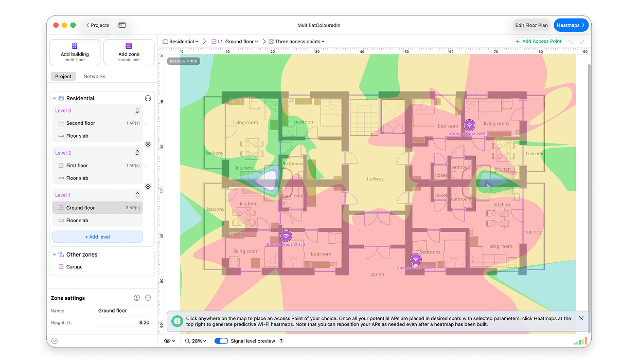
Once you have placed the AP on the map, you can see the predicted signal distribution in real time even before generating heatmaps, including between the levels of a multi-floor building. Dragging the APs will change the signal distribution on the fly. In a multifloor project this will be available only when the levels are aligned.
The real-time signal preview can be switched off with the toggle in the bottom bar.
Please note that the preview will only be applied to those APs that are added to the selected snapshot.
To see the signal level the color on the heatmap represents, move the mouse cursor around the map and look at the color bar at the bottom bar of the app for interpretation.
How to generate heatmaps
After you are done arranging the APs, click the Heatmaps button at the top right to have the predictive heatmaps generated.
When analyzing the generated heatmaps, the two handy and important things you can do are:
You can move your APs around by simply dragging them with a mouse cursor to see the heatmap pattern changes instantly.
You can switch between a variety of heatmap types at the top of the app window to visually analyze different wireless coverage properties.
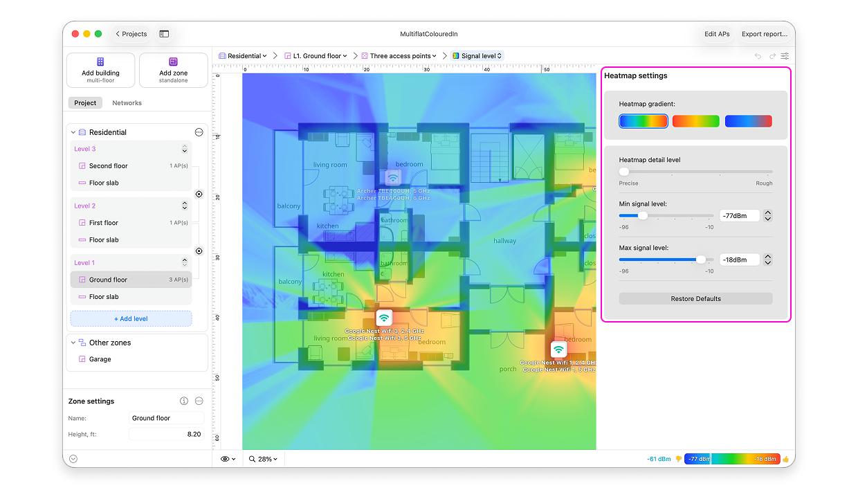
Use the gradient menu on the lower right in order to change the color scheme of your heatmaps, define the minimum and maximum signal levels to be displayed in heatmaps, and set the level of detail of your heatmap, which can assist in faster heatmap generation if you don’t require a high level of detail.
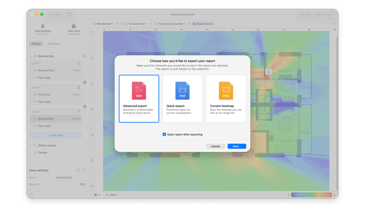
After finishing a predictive survey, you can benefit from NetSpot’s advanced reporting capabilities to present the survey results to a client or colleagues.
You can either choose to export a currently selected heatmap or create a highly customizable enterprise-level report.
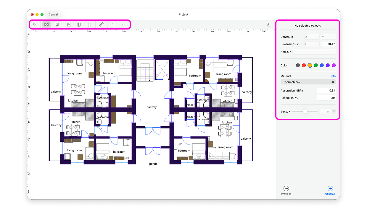
 to select each structural item and manage its properties in the side panel to the right of the canvas.